

Non-linear components and loads in a power system generate' Harmonics'. These elements are characterized by a voltage drop which is not proportional to the current flow. There are a lot of such non-linear loads exist, in components and devices such as;
Harmonic currents may have an adverse effect on different electrical components. These include transformers, switches, capacitors, fuses and relays. The detrimental effects are increased losses and heating and/or excessive dielectric stresses. Electric utilities very often impose high charges when certain maximum levels of harmonic distortion are exceeded.
DISTURBANCES CAUSED BY HARMONIC DETERIORATIONS
Quality of electrical power is downgraded that can disturb sensitive loads,
Increasing in rms current that cause overload in distribution networks,
Increasing in voltage value
Vibration and overload on devices and equipments that cause premature ageing,
Power loss and failures in capacitors
Failures in computers and electronic devices
Overheat on cables and devices,
Quality of the signal transmission incommunication networks and on telephone lines is downgraded
Mono phase loads cause cumulative increasing in third-order harmonics and it causes overloads in neutral conductors
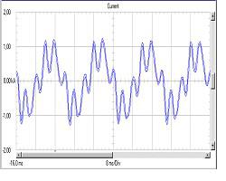
Harmonic currents of a compensation system - without harmonic filter

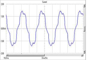
Harmonic currents of a compensation system - with harmonic filter

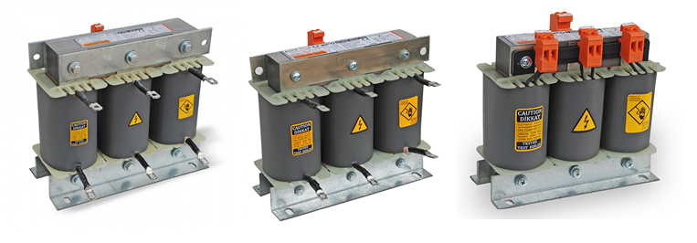
Choosing correct filters for the capacitors in a compensation system is crucial because choosing incorrect filter for the capacitor may shift the resonance frequency of the system and it decreases the efficiency of the compensation system.
Output voltage value of a harmonic filter is higher than its input value. Capacitor's voltage value must be chosen according to the filter's output voltage; otherwise the capacitor will be damaged due to the higher output voltage of the filter and keep in mind that in the industrial fields the mains voltage is higher during night.
Designing most effective detuned filter reactor for the compensation system the following information must be given;
1. Utility voltage value
2. Resonance frequency value (134, 189, 210 Hz, or specify)
3. Power and voltage values of the capacitors
ROUTINE TESTS
Following 1... 5 tests are the routine tests that are performed for each filter during the manufacturing process and the other tests (6,7 and 8) are performed upon request.
Inductance test